Getting closer to simulating the real world: Applying ray tracing in games
At Tencent Game Developers Conference, Yuan Xie explored the challenges of applying ray tracing
Before diving into ray tracing ("RT" for short), let's first take a look at how illumination works in the real world.
From the micro-perspective, the surface of an object illuminated by a ray of light is not perfect and smooth but has a lot of small bumps -- we call this a micro-surface. When light hits this uneven surface, the bumpiness causes light to be reflected in different directions, creating nuances in the real world.
Given the huge number of light reflections and their complex pathways, it is extremely demanding from a computational perspective to simulate real-world lighting conditions in this manner. Until recently, the process was typically restricted to images rendered offline.
So, how can we get closer to such real-world lighting in real-time? Traditionally, we have used rasterization, which renders only the parts of a scene that are displayed on the screen (the screen space) by converting the information in a scene into pixels before rendering the final image. The biggest advantage of rasterization is that it's fast, but a lot of off-screen information is lost and because the calculations are not physical simulations of light paths, the end result can look distorted.
In addition to rasterization, we now have the ability to achieve realistic light simulation through RTX real-time ray tracing. For a demonstration of how RTX works, we can look to how it's being implemented in Synced: Off-Planet, a game currently in development at Next Studios. In the following video, "RTX ON" in the upper right corner indicates that ray tracing is on, and "RTX OFF" indicates that ray tracing is off. Let's focus on the two following elements from within the scene:
- Puddles: When RTX is off, puddles on the ground reflect little of the scene since only the screen space is available to be rendered as a reflection. With RTX turned on, even off-screen information is correctly reflected, such as the sky above or lights immediately out of the POV of the scene.
- Wire fence: The wire fence is made using Alpha Test mapping. With RTX Ray Tracing turned on, the shadow of the wire fence has a natural penumbra effect. When RTX is off, the shadow of the wire fence has very clear stepped edges. This is not what we would experience in the real world where the penumbra effect gradually increases as the object gets further from its shadow. This is a sign of the unreality of non-RT approaches to rendering.
Practical application of ray tracing
In real projects, RT usually displays its advantages in four areas: Reflection, Ambient Occlusion (AO), Shadow, and Global Illumination (GI).
- 1. Reflection
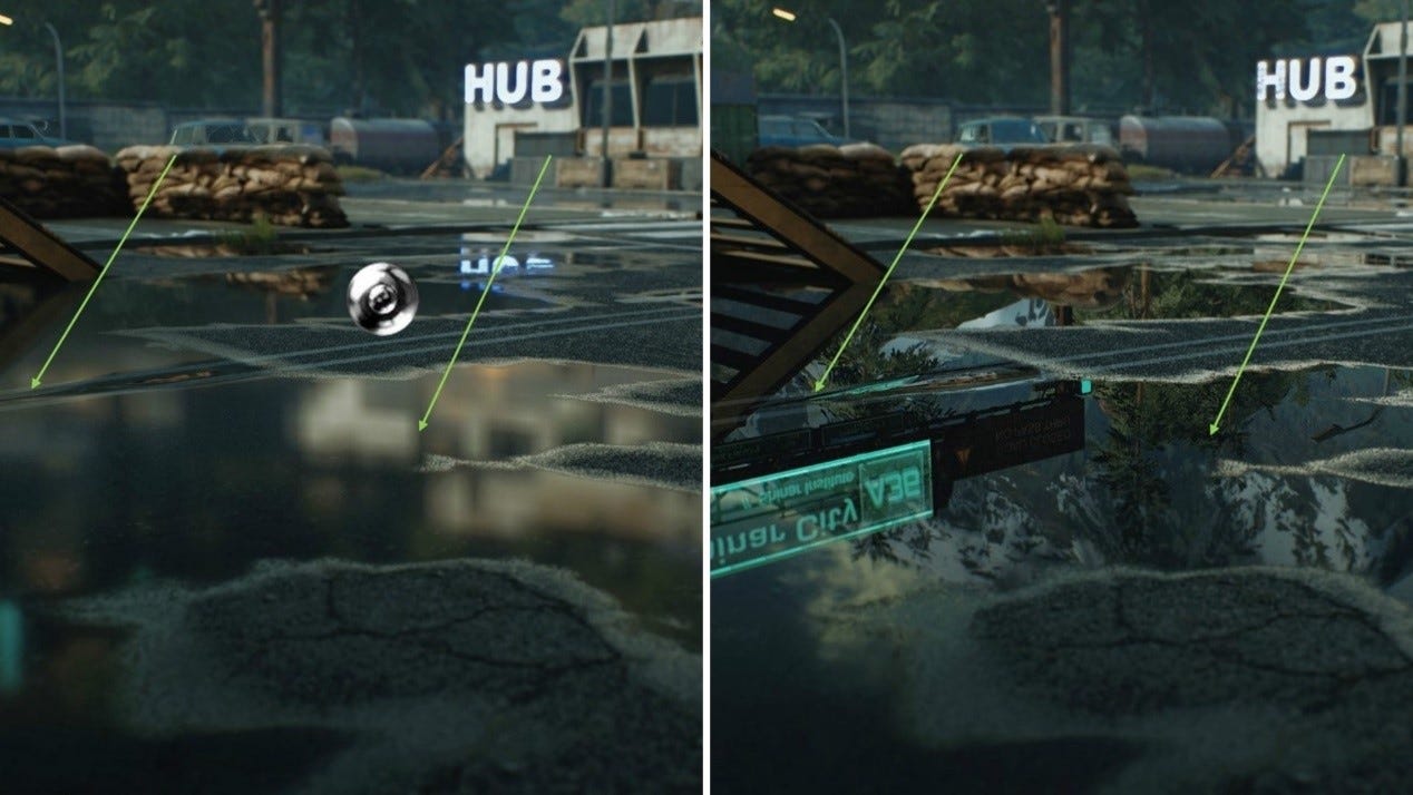
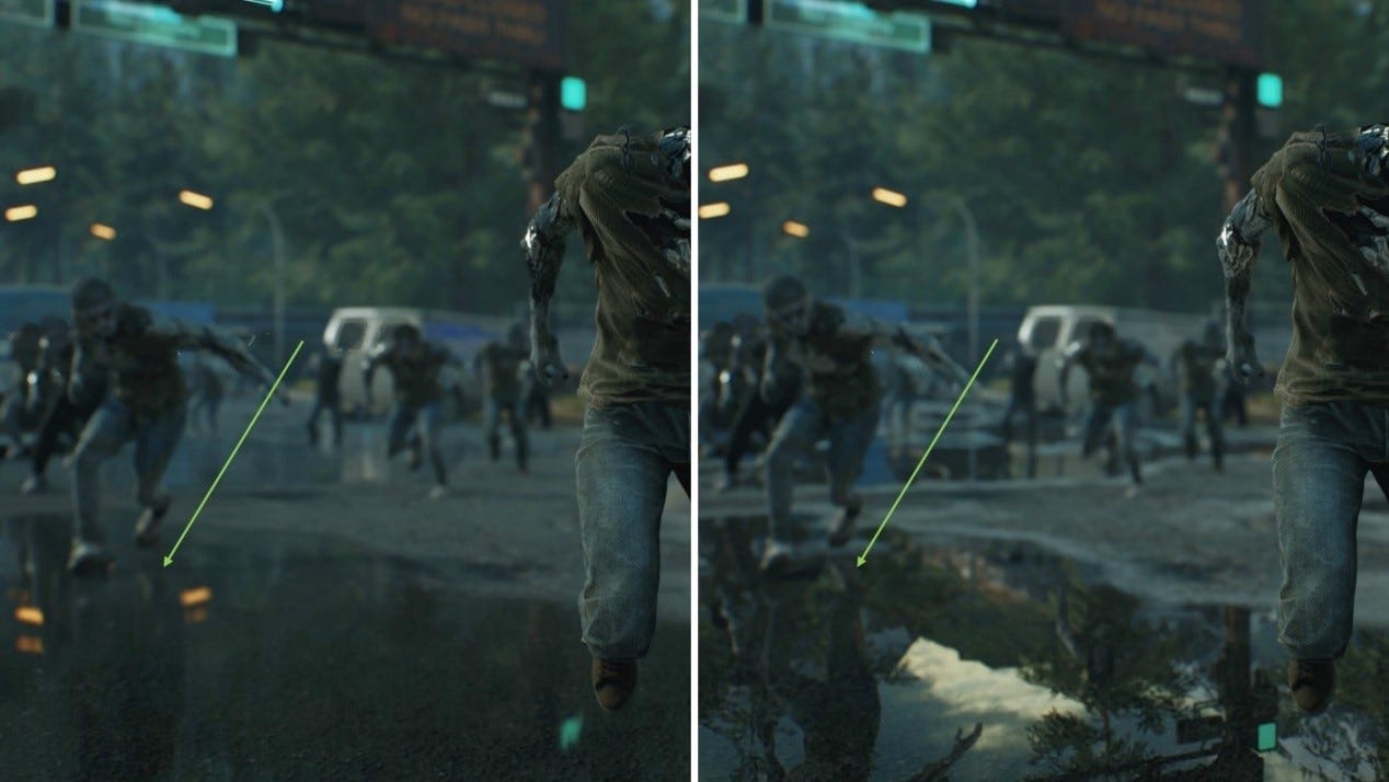
In this screenshot, the focus is on the puddle and the mirror indicated by the green arrows. By looking between the RTX ON and the RTX OFF screenshots, you can see that the screenshot without RT fails to render the reflected yellow railing in the mirror. The RT screenshot also correctly displays the reflected signage in the puddle on the right, but this is missing from the screen space rendering. RT includes more details and the positioning of reflections is highly accurate.
- Sphere reflection capture
As there is often information missing from the screen space reflection, we sometimes use Reflection Capture to grab off-screen information. The white sphere in the center of the RTX OFF screenshot has a baked-in image of the 3D scene, within its radius, and as seen from its central location. This pre-rendered image of the scene can then be used to provide reflections for information that lies outside of the screen space.
However, the disadvantages of Reflection Capture are also obvious: (1) the accurate positioning of reflections limited by the original calculation accuracy; (2) the Reflection Capture image needs to be small to reduce the additional video memory requirements. This can lead to reflections that are vague and blurry, and if we use this technology extensively in a game scene, performance can still be hit by a huge demand on video memory.
Using RT for reflections in an open scene, we see that reflections are rendered crisply and in the correct location, and that the demand on video memory is reduced.
- Dynamic objects
Sphere Reflection Capture only grabs the static objects in a scene. Dynamic game characters cannot be captured with this method and, to render their reflections, we fall back on screen space reflection, as can be seen on the surface of the water in the image below. When RT is on, the reflections of dynamic objects remain clearly visible as they move.
- Batch rendering
When a scene contains a massive number of AI characters, the material roughness of the characters is typically the same. Here we can perform batch rendering, as used in the following image.
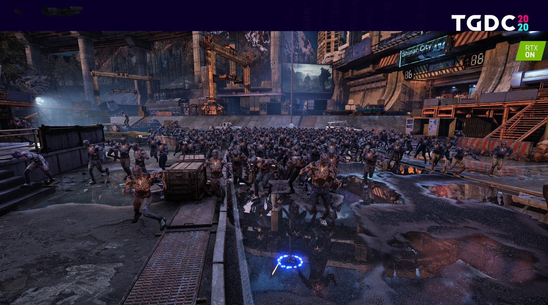
It is worth noting that even with so many characters rendered with RT reflections, a framerate of 50 FPS has still been achieved. RT optimization like this helps to improve the overall performance in rendering such large scenes.
- 2. Ambient Occlusion (AO)
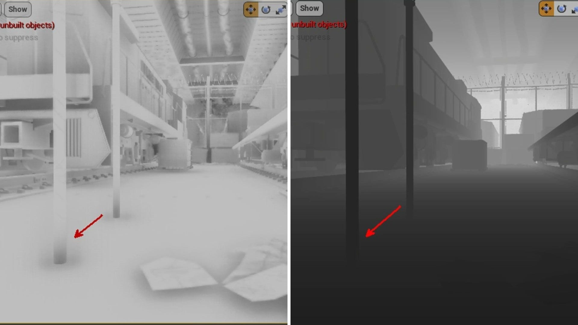
The following image shows the effect of Screen Space AO. There are significant errors in this high elevation view. The Screen Space AO next to the column is calculated from the depth map which is measured from the viewpoint. The calculation compares the depth values of the pixels of the front and rear surfaces.
When the difference between the two depths is less than the sampling radius of the AO, it is assumed that the front object occludes the ambient light reaching the rear object, and an AO effect is generated. In this high elevation view, the angle decreases the difference in depth between the surfaces and the calculation interprets the pole as being closer to the ground, producing this erroneous occlusion effect.
When the scene is viewed from a low elevation, the errors are somewhat reduced. This is because the difference between the depth values of the surfaces is greater when viewed horizontally. There is a smaller area of the screen where the difference is below the sampling radius, and a corresponding decrease in the area of erroneous occlusion. In the RTX ON screenshot, AO is ray traced with algorithms that simulate the physics-the ambient occlusion is highly realistic.
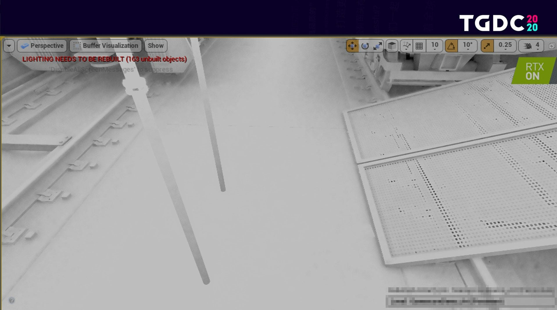
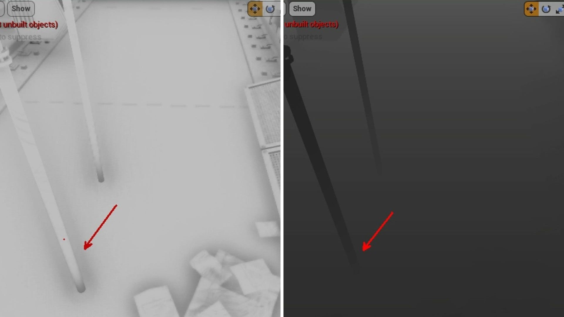
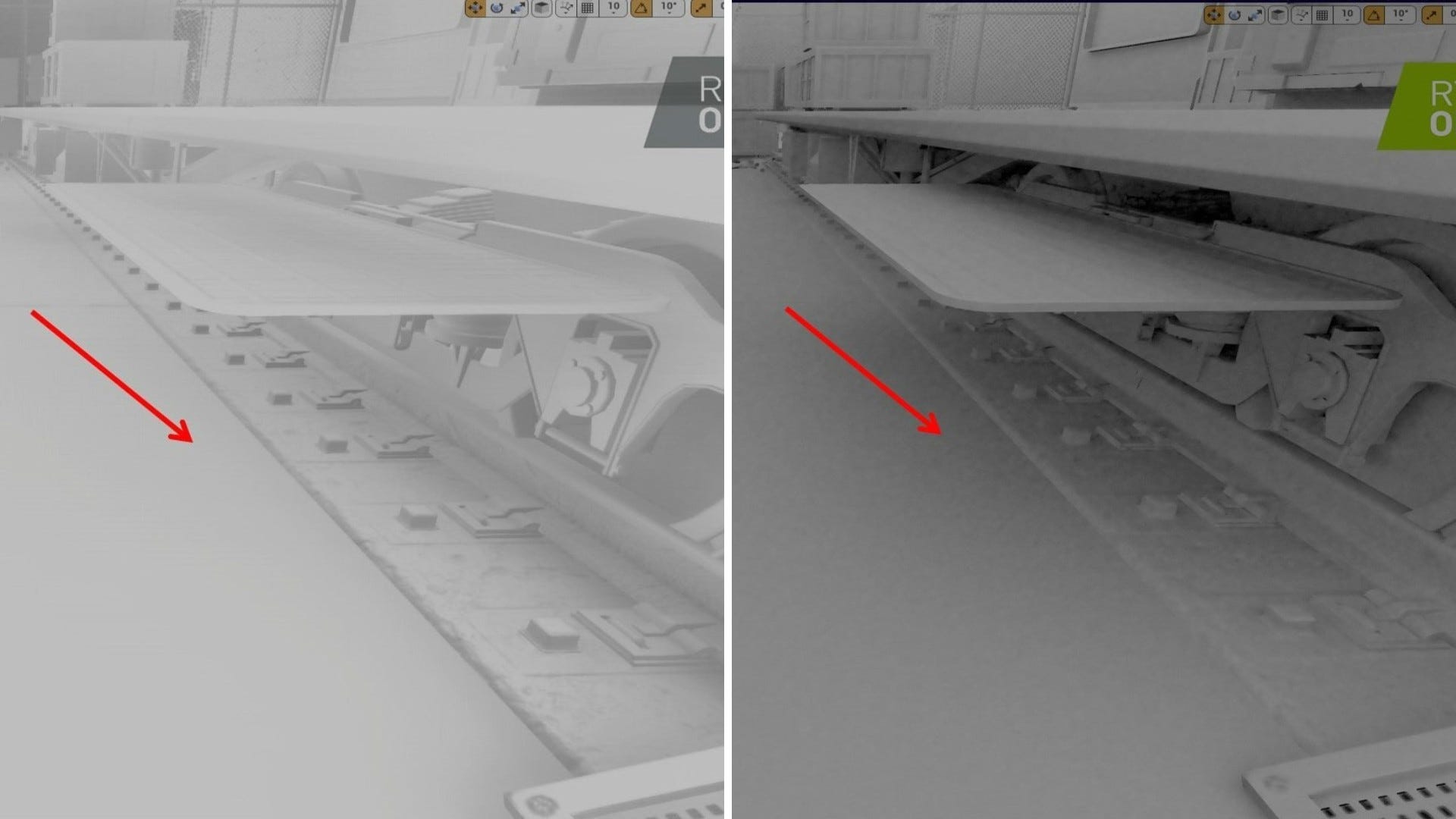
The following image shows a common issue we encounter with Screen Space AO: the area indicated by the red arrow has no visible AO effect. The bottom of the overhanging plate is not visible on screen and is therefore outside the scope of the screen space. This means that there is no depth value available for that surface and its ambient occlusion of the ground cannot be calculated. On the other hand, all such calculations are more realistic under Ray Tracing AO.
- 3. Shadow
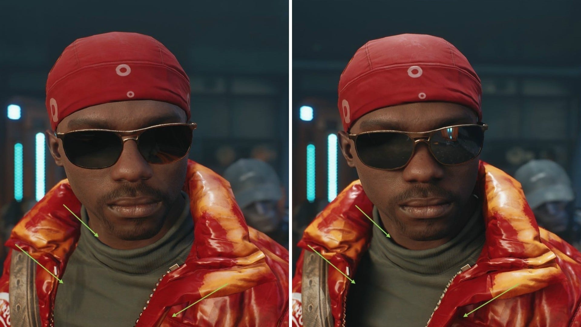
In the following image, where RT is off, the character is lit by a single spotlight. We used CSM projection for the light source, and Contact Shadow was turned on. Despite this, the character's clothing and sunglasses lack a clear delineation between light and shadow. Items seem to float on the character and there is an overall lack of three-dimensionality.
After turning on RT, the character's clothing gains in three-dimensionality, and shadows have a visible penumbra effect. Even the collar casts a clear, thin shadow on the neck and the shadows cast by the sunglasses are close to the real effect. This is the difference between ray-traced and conventional shadows.
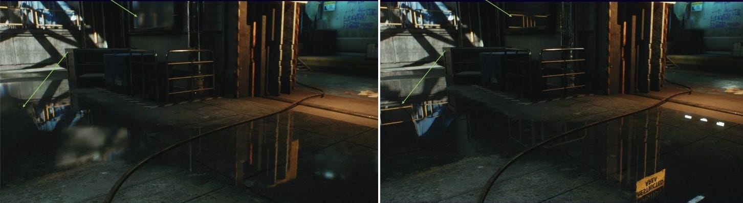
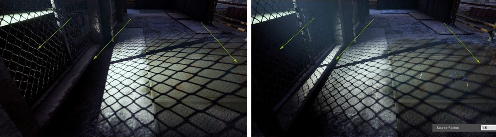
The image below is a screenshot of a scene. Let's focus on the parts indicated by the three green arrows: (1) the area under the left arrow is obviously located in the darkest shadow, but the wire fence is still brightly lit along one edge; (2) the shadows cast on the ground by the structure of the door frame, indicated by the middle arrow, are not correct; (3) the shadows cast by the wire fence, indicated by the right arrow, have a sharp outline-we do not see the penumbra effect we would expect when a shadow is far from the object casting it.
All three areas are changed greatly after turning on RT: that part of the wire fence is now in deep shadow; the door frame is correctly lit and shadows fall as we would expect; and the penumbra effect on the fence shadow now increases realistically with distance.
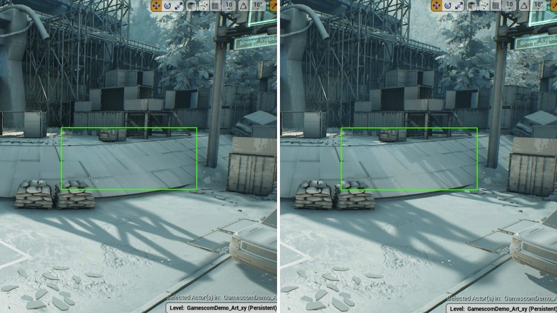
This next image is also a screenshot that is traditionally lit. Look at the area in the green box. Despite the use of CSM projection, the area is still entirely in shadow without any detail. This environment includes many high scaffold structures. The complex shadows cast by these are only accurately projected after turning on RT.
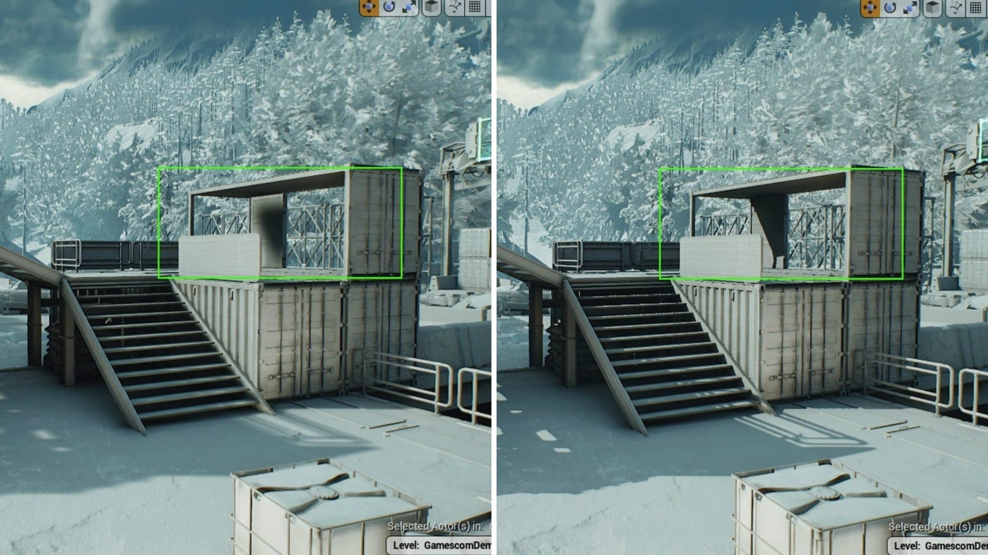
Conventional CSM shadows also lead to another common issue we can see within the green box in the following image. When the shadow to be cast is far from the viewpoint, the Shadow Maps is switched to a lower resolution for performance considerations. This can blur the shadow and give the impression, from our perspective, of light leaking into the container.
RT shadows, on the other hand, are highly accurate. Since CSM is based on simulations, we can increase quality by sacrificing performance. In actual games, the objective is to find a balance between visual effect and performance.
- 4. Global illumination (GI)
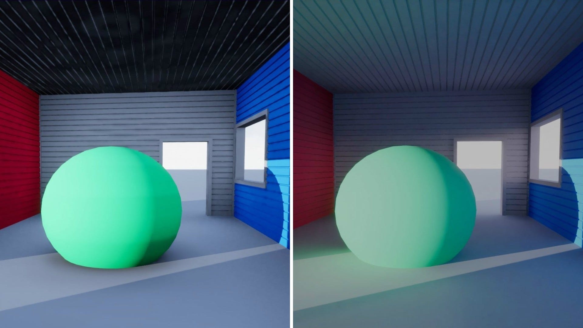
In the picture below, a green ball is placed in a small, simple house, with two light sources in the scene: Sky Light and Directional Light. When RT is off, we can see that the overall effect is that the interior feels very flat. The scene lacks a sense of volume without masking the diffuse reflection. After turning on RT, we can see the huge difference that GI brings to the images.
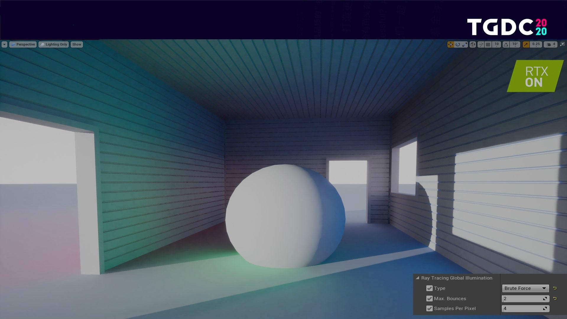
Let's take a look at this scene with GI again, this time in lighting mode. Firstly, GI produces diffuse shading in the room which brings a sense of volume. Secondly, after one or two bounces the light rays reflecting off the sphere project some of its green coloring onto surrounding objects. Furthermore, the parameter in the lower right corner shows that this level of effect was achieved by using no more than 2 bounces.
However, we haven't used RTGI on Synced: Off-Planet for two reasons: (1) our development team has their own dynamic GI system; (2) once dynamic GI is turned on, performance is still the biggest challenge we face -- we may be forced to reduce quality when we can't meet our performance requirements, and this can introduce noise into RTGI. So, for these reasons, we have not used RTGI directly in the project, yet.
Optimization - The power that drives the implementation of ray tracing
Although the visual advantages of ray tracing in real game projects are already well-known, the challenges ahead lie in optimization. If we cannot optimize RT to meet the performance standards we require, it will be difficult to implement in real game projects. Next, we'll discuss 3 challenges that RT faces, and some approaches for successful optimization.
- 1. FPS drops as bounces increase
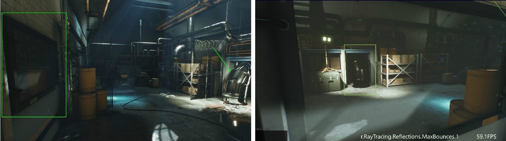
As can be seen in the image below, there's a mirror in the green box on the left and a shiny metal duct under the arrow on the right. However, if you change the point of view, and look at the metal duct in the mirror, you find that the duct has turned black.
To see the duct reflected in the mirror, the light must have bounced once. (We see this in the indicated "MaxBounces.") And this explains why the duct is black. If we want to see the reflection on the duct when looking at its likeness in the mirror, we need two bounces! At this moment, you can see in the upper right corner that the FPS is close to 60.
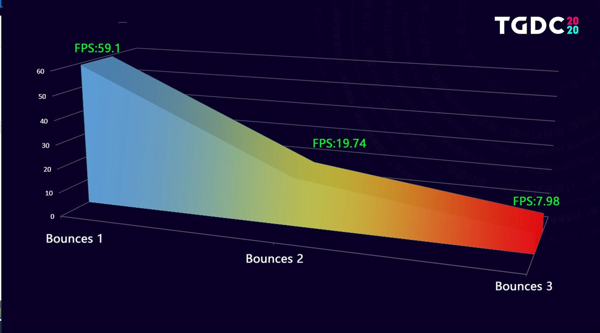
Now we increase the number of bounces to 2. The details of the duct and surrounding objects are rendered accurately, but the FPS dives to 19.7. With the number of bounces increased to 3, the picture doesn't change much at all, but the FPS drops further to 7.98.
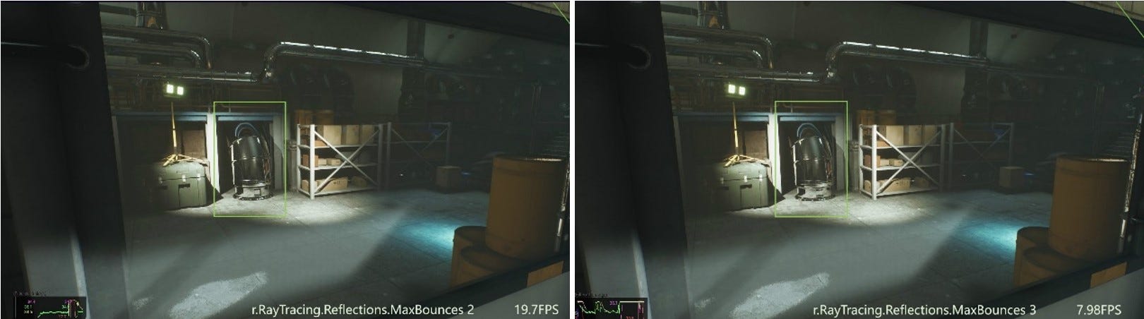
Obviously, the FPS drops greatly as the number of bounces increases.
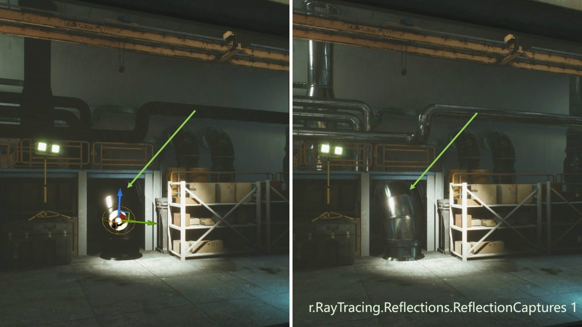
How do we balance this? One solution is to add a Spherical Reflection Capture near the duct to grab static scene information from the vicinity, and then use that to improve the visual effect instead of using the second bounce of RT. This strikes a balance between visual effects and performance and is an applicable approach for scenes with many mirrors and metals.
- 2. Reflected rough surfaces producing low visual effect
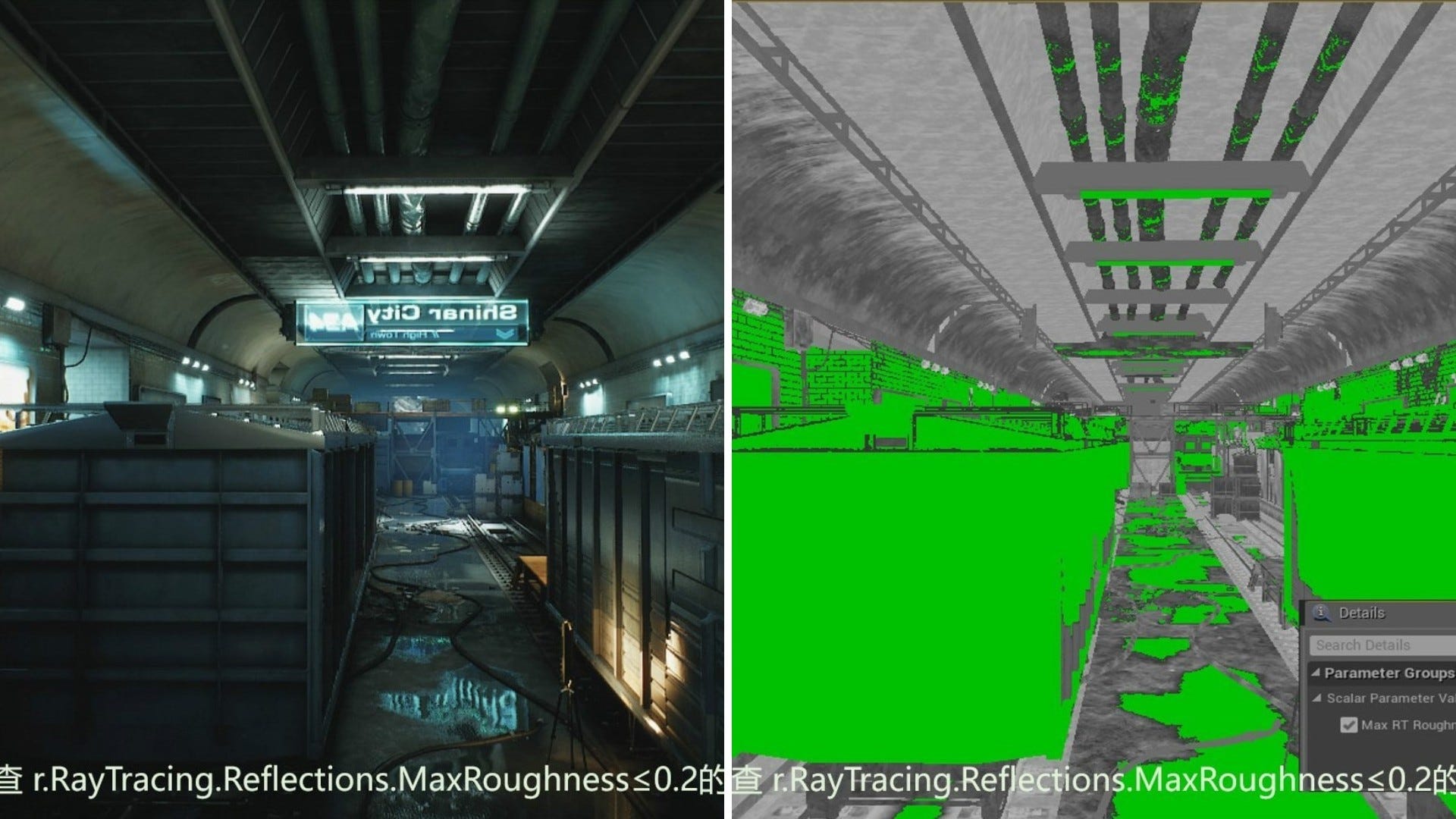
RT reflection makes the required number of bounces regardless of the roughness of the objects, but reflections of an object with very rough surfaces provide little improvement to the visual effect. This is when the Max Reflecting Roughness setting kicks in. We set it so only objects with roughness ≤0.2 make RT reflections, as shown in the image below. For our artists however, how do they tell if the roughness of a material is equal to or lower than 0.2?
We make a post process material, marking in green all the parts that have roughness ≤0.2. This way, our artists can see at a glance which parts have RT reflection, or whether they really need RT reflection on so many parts. Meanwhile, the post process materials provide a better preview for performance control.
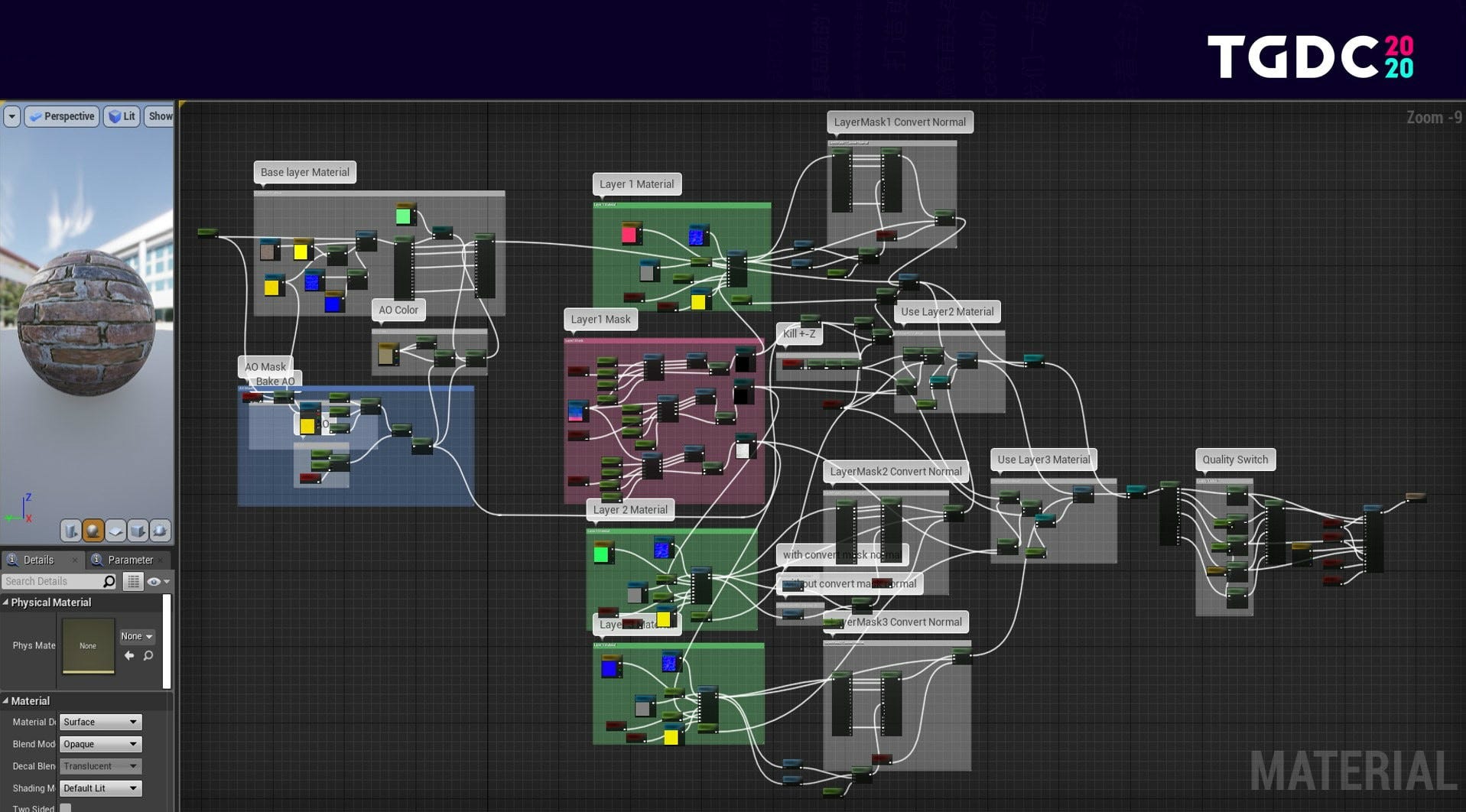
- Parent material and RT quality switch
We've adopted a parent-child material flow in the project. This means our artists can simply generate a child Instance Material from the parent and conveniently apply it after adjusting parameters. The image below shows a node of a material. You can see that some elements of our parent material are richer and more complex than others.
However, complex calculations are less productive on smaller objects. For example, in a scene where you can see the reflection in a mirror of a bottle that has a complex material, the bottle is so small that the complex material doesn't really contribute anything to the scene.
At this point, we introduce the concept of the RT Quality Switch. When we render reflected objects, we don't use the full set of material properties to calculate the RT reflection. Instead, we process only simpler PBR nodes, like Normal Roughness Metallic, which greatly reduces the computation cost.
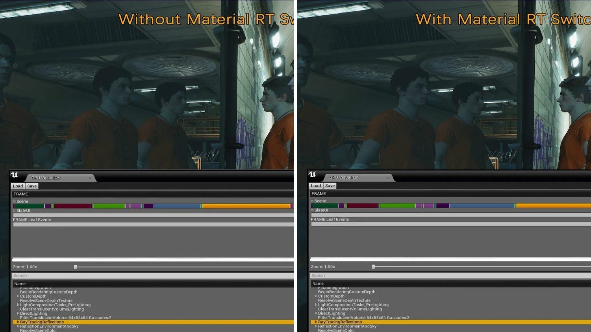
As can be seen in the images below, the clothing on the three characters in front of the mirror have detailed textures. With the RT Quality Switch turned off, the reflected clothing in the mirror also has detailed textures and it takes 4.46 ms to complete the RT reflections. Turning the RT Quality Switch on, fewer details on the reflected clothing are rendered, but the time required for RT reflections is reduced to 4.1 ms, with very little impact on the visual effect.
It is conceivable that if all parent materials were created with optimization nodes for the RT Quality Switch, we could save resources and improve performance in the production of many large scenes.
Additionally, we preset some common RT parameters into the blueprint, and placed the blueprint in the form of a Volume into the intersection of two scenes, as shown in the image below.
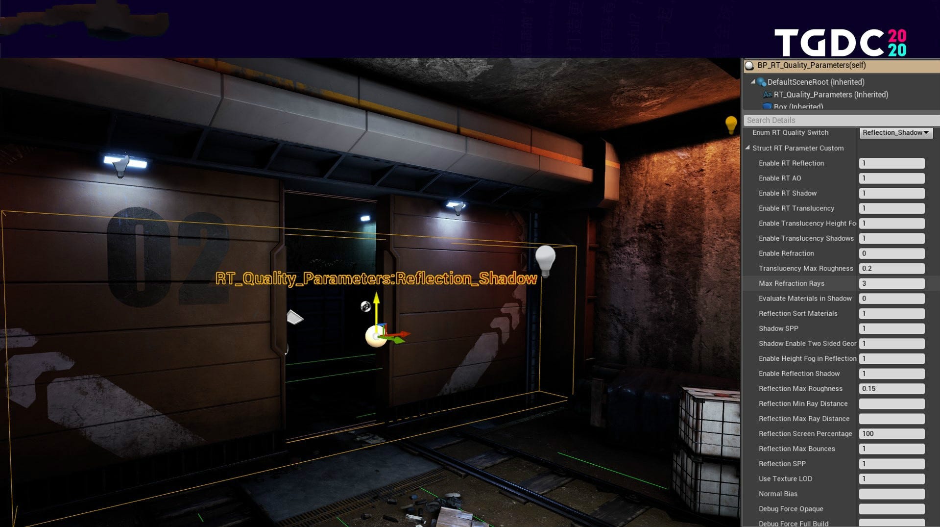
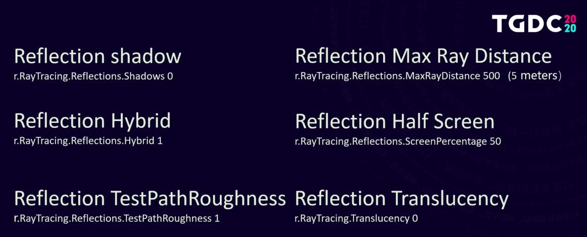
This is an area where an interior and exterior intersect. The lighting information is different between the indoor and outdoor parts; the structure, density and materials of the placed objects also vary greatly. But the Volume we placed here switches different parameters for different environments, balancing the gameplay while assuring the visual effect. Last but not least, here's a list of some common RT optimization methods, commands and parameters used in our projects.
In retrospect, we have encountered many challenges doing R&D for RT. Minimizing the performance hit remains the biggest technical difficulty. The nature of RT is to authentically simulate real-world physics via computation, but our graphics cards, PCs, and their supporting systems have their limits. It is often necessary to sacrifice some visual detail for gains in performance. Optimization is a way to balance these competing demands to the gamer's benefit.
In practical terms and in my opinion, the most important point is that when we choose to deploy RT in our game, we must answer these two questions in the early design stage: In what environments and scenes shall we cater to RT to showcase its advantages? And what scenes needs to be designed specifically for these advantages? I believe that with the development of new hardware, gains in engine efficiency, and the emergence of new technologies, RT will continue to iterate improvements.
Whether it is through conventional rasterization or ray tracing, the goal is always to create better visuals for audiences, and to open doors that bring us closer to the real world.
Having participated in the development of games like Tom Clancy's Rainbow Six and Tom Clancy's Splinter Cell, Yuan Xie is a senior technical artist with Tencent's Next Studios.